The 1959 "Take Five" Soundstage Lesson: Is Your System Smearing the 3D Soundstage?
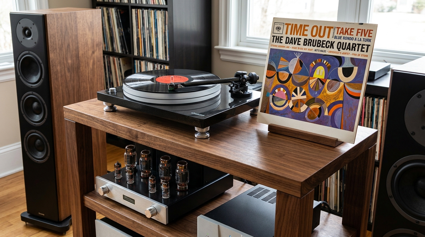
The History: Columbia’s 30th Street Studio ("The Church")
In the summer of 1959, producer Teo Macero and legendary recording engineer Fred Plaut brought the Dave Brubeck Quartet into Columbia Records’ iconic 30th Street Studio in Manhattan. Formerly a late-19th-century Armenian Presbyterian church, the space—affectionately known to musicians as "The Church"—was considered a holy grail of architectural acoustics.
Measuring roughly 100 feet long, 50 feet wide, and boasting massive 50-foot vaulted ceilings, the studio provided an unheard-of 100,000+ cubic feet of volume. The combination of weathered wood flooring, uninsulated plaster walls, and soaring vertical space created a rich, long natural reverberation decay that wrapped around instruments without ever smearing their transient attack.
Unlike modern production—which relies on deadened, heavily insulated booths and artificial digital reverb—Plaut used the physical room itself as an active musical instrument.
Fred Plaut’s Spatial Microphone Placement
Fred Plaut was a master of minimalist, high-yield microphoning. Rather than smothering the band with close-up microphones and artificial isolation baffles, Plaut positioned the quartet across the wood floor to capture true physical distance and 3D stage geometry:

The 3D Listening Test:
- Joe Morello’s Drum Kit (Far Left): Plaut placed a vintage Neumann tube condenser microphone above the kit. By backing the mic slightly off the ride cymbal, he captured not just the sharp transient snap of Morello’s stick technique, but the natural floor-and-ceiling reflections of the church.
- Dave Brubeck’s Piano (Far Right): Plaut positioned Brubeck’s grand piano on the opposite side of the room, angled away from the drums to minimize bleed while allowing the piano’s soundboard resonance to bloom in its own dedicated acoustic zone.
- Eugene Wright’s Upright Bass (Center Anchor): Plaut placed a single directional tube mic close to the soundboard of Wright’s double bass. Positioned centrally, this anchored the 5/4 rhythm, providing a weight, warmth, and physical body that feels physically rooted in the room.
- Paul Desmond’s Alto Saxophone (Front-Center / 3–4 Feet Out):Plaut positioned a Neumann tube condenser roughly 3 to 4 feet in front of Desmond’s horn. In a studio measuring 100,000 cubic feet, 4 feet was the "sweet spot"—close enough to capture 85% direct, intimate horn energy (reed breath and transient attack), yet far enough to let the acoustic pressure bloom before hitting the room's timber boundaries. When played back on a resolved system, this high ratio of direct sound against subtle room decay causes Desmond’s sax to project forward 3 feet in front of your speakers into your room. The Natural Room Acoustics & Micro-Decay Cues
When listening to a well-mastered press of "Take Five", your brain relies on two critical cues to construct a 3D stage in your room: Time Arrival (Phase) and Micro-Decay Tail Signals.
Because Plaut allowed natural leakage between the open microphones across the massive studio floor, the acoustic bounce of Desmond’s saxophone hit the room boundaries and entered the drum and piano microphones milliseconds after the direct sound.
This tiny delay—known as ambient room decay—is what gives "Take Five" its jaw-dropping sense of depth. In a fully resolved Hi-Fi system, these delicate, low-level room decay tails tell your brain: "This isn't coming from a box speaker 6 feet away; this is happening inside a massive acoustic room."
Why Does a High-End System Sound Flat or 2D?
You can spend tens of thousands of dollars on high-resolution DACs, reference speakers, and pristine acoustic treatments, yet still end up with a soundstage that feels locked to the physical speaker cabinets.
When a system fails to project Paul Desmond’s saxophone into the room or flattens the natural studio reverberation of Columbia’s 30th Street Studio, it is rarely a speaker problem.
In 90% of bench diagnostics, a 2D soundstage is caused by invisible electrical bottlenecks in your signal and power architecture. Here are the three primary technical root causes that choke spatial depth:
1. Parasitic AC Potential (Chassis Ground Noise)
Every audio component connected to mains AC power generates a subtle, parasitic AC voltage potential across its metal chassis. Caused by stray capacitance in power transformers and mains leakage currents, this stray potential looks for the path of least resistance to ground.
When your preamplifier, source, and power amplifier are interconnected via RCA cables, these parasitic AC currents travel through the signal ground shield of the RCA.
This unwanted current riding on your signal reference plane raises the system's noise floor. Spatial cues—such as the subtle room decay of Fred Plaut’s open microphones—are extremely low-level micro-signals. When parasitic AC potential pollutes the ground reference, these delicate micro-reflections are buried beneath the noise floor, flattening 3D stage depth into a 2D plane.
2. Microscopic Contact Resistance & Oxidation
An RCA or XLR connection may feel mechanically tight, but at a microscopic level, metal surfaces are full of peaks and valleys (asperities). Over time, atmospheric exposure creates a thin layer of metal oxidation across your jack sleeves, pin sockets, and grounding lugs.
This oxidation layer introduces microscopic contact resistance and non-linear junction effects:
- Micro-Dynamic Smearing: Low-level transient signals (like Joe Morello’s delicate cymbal brushwork) lack the current drive to cleanly pass through oxide barriers without dynamic compression.
- Ground Reference Drift: Small voltage drops across oxidized ground returns corrupt the absolute zero-volt reference between stages, causing the soundstage center image to lose its sharp pin-point focus.
Cleaning and treating contacts isn't just routine maintenance—it restores the physical contact area required for uncompressed micro-transients and razor-sharp vocal positioning.

3. Micro-Phase Smearing Across the Signal Path
Human spatial hearing relies on tiny timing differences—down to microseconds—between your left and right ears (Interaural Time Differences or ITD). This is how your brain calculates the physical distance and angle of an instrument on stage.
Micro-phase smearing occurs when subtle phase delays corrupt the signal as it travels through your component chain. Common bench culprits include:
- Asymmetric Ground Return Impedance: Unequal resistance or inductance in left vs. right ground paths alters the high-frequency phase response between channels.
- Decoupling & Power Rail Inconsistencies: Weak power supply rail decoupling or aging filter capacitors allow voltage ripple to modulate the signal path, causing minute phase shifts in the upper-midrange and treble.
When the phase integrity of subtle room reflections is altered by even a fraction of a millisecond, your brain can no longer calculate room boundaries. The depth cues collapse, turning a holographic 3D performance into a flat, 2D presentation.
Bench Diagnostics: Restoring Black Backgrounds & Acoustic Decay
In high-fidelity reproduction, a "black background" is not just a poetic metaphor—it is a physical measurement of dynamic range and signal-to-noise ratio at ultra-low levels.
When your system's noise floor sits at , every acoustic cue encoded between and is completely masked. In the case of Fred Plaut’s 1959 recording of "Take Five", those buried micro-signals contain the entire acoustic geometry of Columbia’s 30th Street Studio: the timber wall reflections, the height of the 50-foot vaulted ceiling, and the long, natural decay tails of Paul Desmond’s saxophone.
Restoring those spatial cues requires systematic bench diagnostics aimed at lowering parasitic noise and preserving phase symmetry.
1. Measuring and Neutralizing Parasitic AC Chassis Potential
Before swapping cables or tube sets, you must audit the parasitic AC potential sitting on your component chassis:
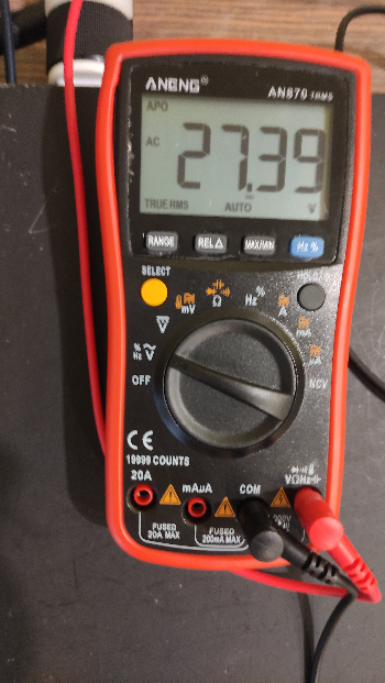
- The Bench Diagnostic: Set a high-impedance Digital Multimeter (DMM) to AC Volts. Disconnect all interconnect cables so the component is floating. Touch one probe to the clean metal chassis and the other to safety earth ground.
- The Fix: Measure the AC leakage potential with the AC mains plug in its standard orientation, then flip the mains plug 180° (if non-polarized or using an isolation setup) and re-measure. Orient the plug to achieve the lowest measured chassis voltage. Minimizing stray chassis potential prevents parasitic ground loop currents from riding across your interconnect shields.
2. Cleaning and Treating Junction Interfaces for Zero Contact Resistance
Oxidation and micro-contaminants create non-linear junction resistance across both RCA and XLR interfaces:
- RCA Lines: High contact resistance on the outer ground shield elevates the signal ground reference plane, driving noise directly into the input stage.
- XLR Lines: Unmatched contact resistance between Pin 2 (Hot) and Pin 3 (Cold) degrades your receiver's Common-Mode Rejection Ratio (CMRR), allowing power supply ripple and stray EMI to bleed into the differential signal.
- The Bench Diagnostic: Inspect all jack sleeves and pin sockets under lighting for dulling or tarnish. Deoxidize all contact surfaces with a specialized contact cleaner (such as DeoxIT D5/Gold), ensuring both the ground sleeves and female socket pins are burnished clean.
3. Power Rail Decoupling & Ground Plane Geometry
Subtle micro-phase smearing often originates inside the power supply rails of your preamplifier or DAC. As dynamic passages demand current, inadequate rail decoupling allows AC ripple to modulate the local ground reference.
- Local Decoupling: Placing high-speed, low-ESR film bypass capacitors directly across local op-amp supply pins or tube plate loads stabilizes high-frequency current loops.
- Ground Return Paths: Ensure signal star-ground points are strictly isolated from high-current AC power supply returns to prevent heavy charging pulses from corrupting the delicate zero-volt signal reference.
The Result: True 3D Spatial Layering
When you eliminate parasitic chassis leakage, balance line impedances, and drop your bench noise floor below , the audible transformation is immediate:
- The Black Background Emerges: The "hiss" and grain between musical notes disappear, creating stark contrast against silence.
- Micro-Decay Tails Unfold: As Paul Desmond stops blowing his saxophone note, you hear the room reverberation slowly tail off into the far corners of the studio space rather than cutting off abruptly.
- Pin-Point 3D Imaging: Instruments stop overlapping on a flat line. The drums drop back to the far left, the piano locks to the far right, the bass anchors the deep center, and the alto sax floats 3 to 4 feet out into your room with physical, holographic weight.
Free DIY Bench Guide
Is your noise floor hiding low-level room reflections and flattening your stage?
Audit your power rails, ground returns, and contact interfaces on the bench today with our step-by-step diagnostic guide.