The 27.39 V Floating Ground Bottleneck
The 27.39 V Floating Ground Bottleneck: How Parasitic AC Potential Destroys Hi-Fi Soundstage
Is a hidden ground potential difference ruining your audio soundstage?
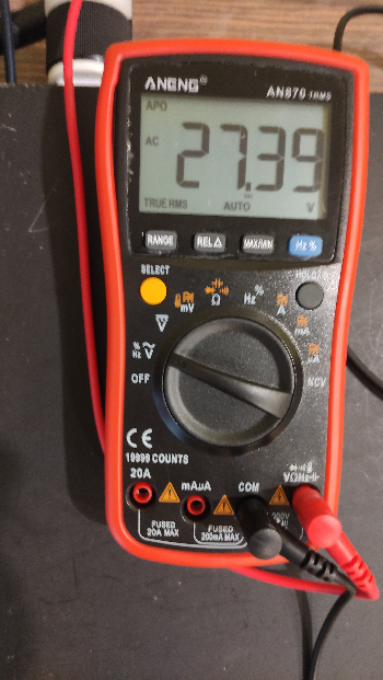
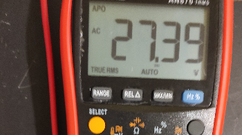
I recently measured 27.39 Volts AC between a CD player and an amplifier chassis on the bench—with zero signal interconnect cables plugged in .
If you think your system operates against a completely "black background," grab a digital multimeter, set it to AC Volts, and measure the AC potential between your component chassis before connecting your interconnects . You might be shocked by what is silently degrading your spatial resolution and micro-dynamics .
Where Does This 27.39 V AC Come From?
This floating potential is caused by stray capacitive coupling and primary-to-secondary mains transformer leakage .
When two audio components float at different AC potentials, connecting them via standard RCA interconnect cables forces high-frequency equalization currents to flow directly through the outer cable shield .
This parasitic ground loop current doesn't always show up as an obvious 50Hz or 60Hz mains hum . Instead, it creates silent intermodulation noise that rides along your signal return path :
- Elevated Noise Floor: Subtle room reflections, instrument decays, and micro-detail get buried under background hash .
- Smeared Center Image: Lead vocals lose their pinpoint laser focus and spill loosely into the left and right channels .
- Compressed Dynamic Slam: Fast transient attacks—like drum rimshots or acoustic guitar plucks—feel dull, soft, and rounded off .
How to Audit Your Ground Zero Integrity on the Bench
- Unplug Interconnects: Disconnect all audio interconnect cables (RCAs or XLRs) between your source gear and amplifier .
- Power On: Turn on your components and set your Digital Multimeter (DMM) to AC Volts .
- Measure Chassis Potential: Touch one probe to a clean metallic chassis screw on Component A and the other probe to Component B .
- Evaluate: If you measure more than a few millivolts AC (such as 10V to 30V AC), your components are floating at vastly different potentials, driving parasitic loop currents through your signal paths .
How to Fix It on Your Bench
Step 1: Perform the AC Phase Flip Test
Flip the 2-pin AC plug orientation of your source component by 180 degrees and re-measure the AC chassis potential . Keep the plug in the orientation that yields the lowest AC voltage reading on your multimeter .
Step 2: Establish a True Zero-Ohm Chassis Bond
If a voltage differential remains, run a heavy-gauge (14–16 AWG) stranded copper ground strap directly between the chassis earth screws of the components . This provides a ultra-low impedance path to bleed off leakage currents before they ever reach your delicate signal cable shields .
Take Your System Diagnostics Deeper
Draining stray potential differences lowers your system noise floor, revealing razor-sharp 3D imaging, blacker backgrounds, and effortless decay .
Want the complete step-by-step diagnostic process to audit your power rails, ground returns, and contact resistance?